Custom magnetics / SMPS development

Custom high-frequency transformers
built for the next bench test.

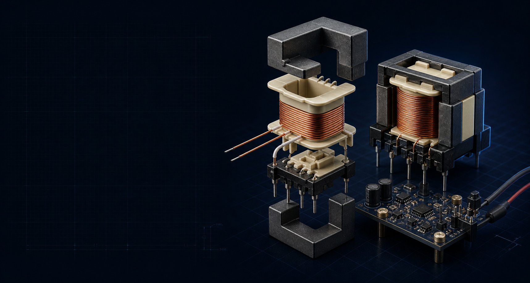
Herder Elektronische Systemen develops custom transformer prototypes for switch-mode power supplies, connecting electrical requirements, core selection, winding construction, 3D documentation and measured bench behavior.

FLYBACKSMPS MAGNETICSCUSTOM WINDING3D MODELINGPROTOTYPE VALIDATION

01 / What can be developed

Magnetics shaped
around the converter.

  • Flyback transformer prototypes
  • High-frequency isolation transformers
  • Custom turns ratios
  • Primary, secondary and auxiliary windings
  • Gapped ferrite-core prototypes
  • RM, EE, EFD, ETD and other practical ferrite geometries where suitable
  • Hand-wound engineering samples
  • Small prototype quantities
  • Revisions of existing transformer designs
  • Replacement prototypes where sufficient source information is available

Feasibility depends on topology, input range, output requirements, switching frequency, isolation needs, core geometry, winding window, thermal limits, safety expectations and component availability.

02 / Customer inputs

Bring the electrical
boundary.

Requirements panelStart with what is known.
  • Converter topology
  • Input-voltage range
  • Output voltage and current
  • Switching frequency
  • Controller or primary-side IC
  • Target power
  • Number of windings
  • Auxiliary-bias requirements
  • Isolation requirement
  • Core or size constraints
  • Expected duty cycle
  • Existing schematic
  • Existing transformer data
  • Target quantity
  • Intended environment
  • Safety or qualification expectations
Do not send sensitive design files through the initial email.

Secure file exchange can be arranged after the first discussion.

03 / Engineering workflow

From requirements
to a reviewable prototype.

  1. 01

    Define the electrical boundary

    Confirm topology, voltage, current, frequency, duty cycle and isolation needs.

  2. 02

    Select the magnetic structure

    Review core material, geometry, effective area, winding window and gap approach.

  3. 03

    Develop the winding construction

    Define turns, wire, winding order, insulation assumptions, polarity and pin assignment.

  4. 04

    Model and document the assembly

    Produce construction drawings, winding-stack visuals and 3D reference models where included.

  5. 05

    Wind and inspect the prototype

    Build the engineering sample and record construction details.

  6. 06

    Measure and revise

    Review inductance, DCR, leakage, switching behavior and converter-level observations where test access permits.

04 / 3D transformer modeling

3D models that make the construction
reviewable.

Parametric models can make transformer construction, pin orientation, winding space and mechanical integration easier to inspect before or after the first physical build.

  • Parametric modeling of cores, bobbins, pins and assemblies
  • Simplified winding-layer models
  • Insulation-stack visualization
  • Core-gap representation
  • Winding-window utilization views
  • Exploded assembly views
  • Pin numbering and polarity orientation
  • PCB-mounted clearance review
  • Enclosure and neighboring-component clearance review
  • Dimensioned reference drawings
  • Technical renders for documentation
Potential CAD deliverables
Native parametric modelSTEP exportDimensioned drawingExploded viewWinding-stack illustrationPinout and polarity diagramPCB clearance view

The 3D model documents physical construction and integration. It does not by itself validate electromagnetic performance, insulation coordination, thermal behavior, regulatory compliance, manufacturability or production repeatability.

Complete transformer assembly
Exploded core and bobbin view
Winding and insulation stack
PCB-mounted clearance view
Dimensioned reference drawing

05 / Prototype deliverables

A prototype with enough
information to continue.

  • Wound transformer prototype
  • Winding specification
  • Turns table
  • Wire and insulation notes
  • Core and gap information
  • Pinout and polarity
  • Inductance measurements
  • DCR measurements
  • Leakage-inductance observations
  • Construction notes
  • 3D construction model where included
  • Bench-test notes
  • Revision recommendations

Exact deliverables depend on the agreed scope, available test access and whether the request covers transformer construction only or converter-level evaluation.

06 / Evidence and validation

Measurements with the
test conditions attached.

Caption / provenance / revision
Turns, polarity and pin assignment
Core geometry and gap detail
Transformer in converter context
Instrument / date / test condition
Instrument / date / winding
Winding condition and method
Operating point / probe / revision
Input, load and thermal context
Model revision and CAD provenance

Every evidence block should identify source or provenance, instrument, test date, operating condition and prototype revision. No values, plots, dimensions, photographs or validation claims are invented here.

Prototype magnetics are engineering samples.

Suitability for production, reinforced insulation, regulatory compliance, long-term reliability, thermal performance and manufacturing repeatability requires separate analysis, testing and qualification.

07 / Related work

See the transformer
in converter context.

Start a technical discussion

Bring the
converter requirements.

Share the topology, electrical targets, switching frequency, intended quantity and what has already been measured. Secure file exchange can follow the initial discussion.

Discuss a transformer prototype

Or write directly: [email protected]